Showing posts with label Locomotives. Show all posts

Tuesday, 10 December 2024

The Quarry Hunslet 'Alice' class from PDF Models - The Making Of. (Part 2)

Quartering

Taking the cranks as pairs, screw in a 2mm x 10mm countersink screw to each for the front pair and a 2mm x 16mm countersink screw to each for the rear pair. Enlarge slightly the holes in the rods to enable the 2mm bearings to fit freely. Fit the rods to the front cranks and fit to the axles using a 0.9mm allen key. Loosely set the front cranks 90 degrees to each other. Do not over tighten.

Similar to the above, fit the rear cranks 90 degrees to each other. Don't fit the rods to the rear just yet.

Test for free movement and if necessary adjust the cranks until running freely. Then fit the connecting rods and test again.

The footplate can now be fitted. But before doing so, countsink the two front holes before fitting to the chassis using four 2mm x 6mm bolts.


The above photos also include the motor cradle fitted with two 3mm bolts.

The buffer beams were now fitted using two 3mm bolts, screwed directly into the chassis frame (no nut). Like the connecting rods they were painted before fitting with Red Primer and Fiat Red Orange.


Part 3

Thursday, 21 November 2024

The Quarry Hunslet 'Alice' class from PDF Models - The Making Of. (Part 1)

The chassis


Purchased in 2021 from PDF Models, this kit would make a brilliant addition to my fleet of engines. The only difference this time is that there will be no need to charge it up or raise steam before it can be operated.

Although a relatively easy kit to build, I would say it is more for the medium experienced modeller. The instructions lack punctuation, so a good read through and familiarisation with the components before starting is a must. PDF Models also provide contruction videos via their website.

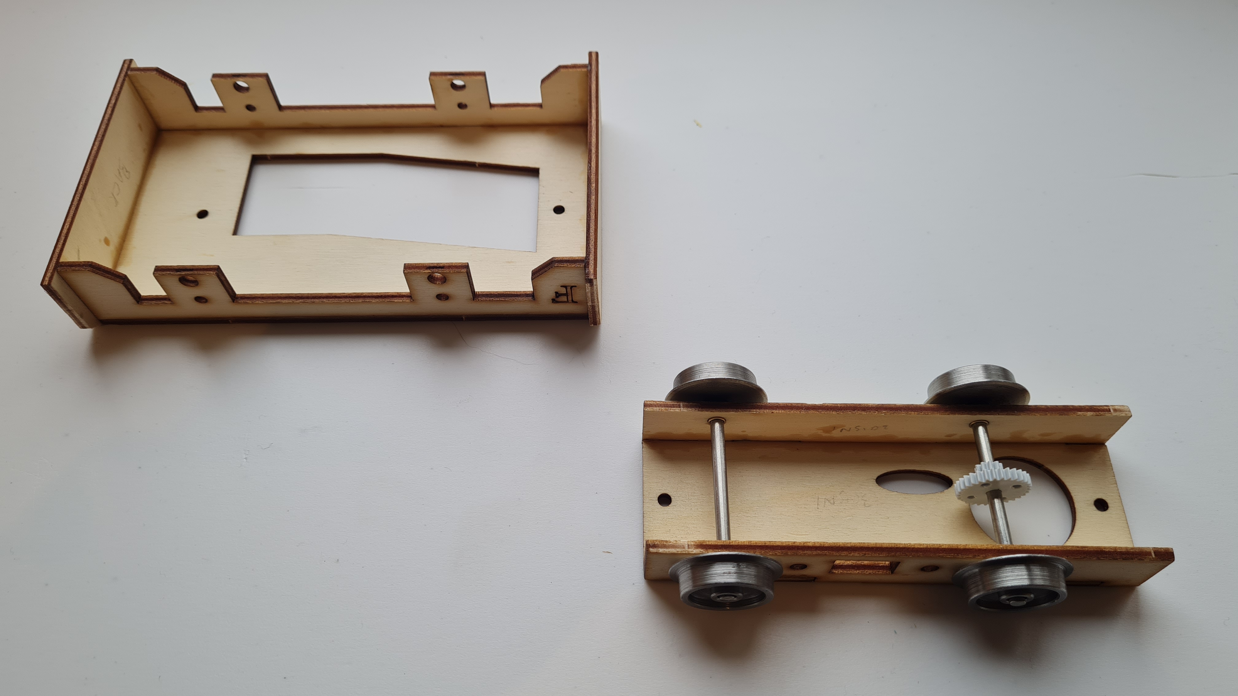
Starting off with the chassis, identfy the two sides and frame spacers. Glue into the spacers 2mm nuts, using the bolts to hold them in place whilst the glue dries. Once set, remove the bolts and paint the chassis parts.


I used Halfords spray cans throughout the making of this model. Here the chassis was given two coats of grey primer and finished with two coats of satin black.

During this process I prepared the two cylinder covers for painting. This involved removing the 3D printing ridges using various grades of sandpaper, starting with 80, 180, 1200 and 2000. It takes some time, but well worth it.


After 24 hours once the paint had hardened, the chassis was bolted together using 8mm bolts.

At this point, the centre cylinder holes were lightly opened up using a 3.2mm drill bit. This enabled the brass cylinder tube to be inserted and glued leaving a protrusion of approximately 7mm at the rear of each cylinder.


In preparation of fitting the cylinders to the chassis, the two holes on the rear of each cylinder were opened up slightly with a 2.5mm drill bit and tapped with the 3mm cap head bolts.

Now to make the cylinder slide bars and mechanism. Take each cross head and glue in the 2mm steel rod. I then temporarily fitted the cylinders to the chassis with cap head bolts. Slide the cross head and rod into the cylinder tube and fit the slide bar holder. Once checked for free movement a spot of glue was applied to the holder and rear cylinder and the slide bars were fitted. Once set, I remove the cylinder from the frame and fitted each connecting rod* using a 2mm x 6mm bolt (but not too tightly as it has to slide freely.) 
*I thought it a good idea to paint the connecting rods before fitting using Red Primer with a top coat of Fiat Red Orange.


Taking the gearbox housing, the bearing holes were opened up to 4mm (drilled) and the bearings fitted. The axle was then slid through the bearings and the gear added. Once happy with its free movement, a spot of glue was daubed onto the outside of the bearings to hold them in place. Once all okay, I tested the movement with a 3v battery before adding a spot of gear oil.


The chassis was now un-screwed and the wheel bearings fitted. Do not attempt to fit these with the chassis screwed together! Fit with a wooden or nylon head modellers hammer making sure that the 'top hat' is on the outside of the frame.


The wheels were next fitted to the axles by pressing them on until a distance of 41mm for 45mm gauge (28mm for 32mm gauge) was achieved. Either use a vice back to back or in my case my nylon headed hammer.


Fit the the chassis back together, slotting in the axles and wheels to complete the frame.


Refit the cylinders with the 3mm cap head bolts.


Tuesday, 19 September 2023

Little Ronnie the Diesel Engine.

This I.P. Engineering model is roughly based upon the O&K MD2 locomotive.

Starting with the sub-frame on which the body will be mounted, buffer beams were added, each with a forty five degree cut across the top corners.

Next the basic rolling chassis was constructed, together with the central gear for the motor.


The kit came with two little screws to mount the two sections together. I may have misunderstood the assembly instructions and couldn't see how they fitted, so I chose to use two small bolts with two threaded nuts. (those used to fit a mains light switch fascia plate). 

Putting the two sections aside, a start was made on the body. Starting with the engine housing, rivet detail was added to the front and two side panels (1/16" x 3/8"). As these would be hidden, they were left untrimmed. Once fixed the panels were glued and made square.


The cab was made in a similar way, again using rivet detail. These were glued in, cut to size and filed, with the cut offs kept for later use.


Both the engine housing and the cab were then glued together and checked for square.

Now was a good time to add the wiring from the motor to the battery pack via the three position switch.

With just a few more steps, the body and chassis are prepared for priming. Using the cardboard profiles included, the engine access doors and window trims were glued in place. The cut-offs from the rivets were added to the doors edge to create the appearance of hinges. Bolt heads were glued in place on the buffer beams. And lastly, an angled frame was centrally fitted to the front of the sub-frame. This will assist later when fixing the body to the sub-frame after painting.


Adding weight and motive adhesion, the cast white metal components were fixed in place on the sub-frame with epoxy resin. The body and sub-frame were subsequently primed with Humbrol grey primer.


The chassis was then spray painted with Halfords Acrylic Satin Black and Halfords Acrylic 'Fiat Red Orange' for the buffer beams. More weight was added once the couplings had been primed and painted.


With the couplings added the cab was presented to the body shop for spraying. Once masked off to protect the interior, the body was painted using Halfords Acrylic 'Peugeot Royal Blue'. Three coats later, the body was left to harden for twenty minutes or so before the tape was removed. Loosely fitted to the chassis, all was checked for appearance.


To enable the roof to be removed, just in case cab detailing was later required, the roof was pre-formed using plastic strips to the contour of the cab. An exhaust was added from SLR Models, secured with two small screws to the bonnet. A drawing pin and bead were used to create an air intake. Primed and painted with Halfords Acrylic Satin Black.


The body was then attached to the chassis using two small black screws fitted into the angled bracket at the front, below the radiator grill. A small block of wood (Jenga) was glued under the seat and then screwed through the chassis into the block.

I selected "Alwin" from Kara's Little Kharacters to be the driver. Painted and fitted onto his lovely soft red plush seat, he was ready to go.


The End.


Tuesday, 28 December 2021

Little Ryan the Diesel Engine

Starting with a P S Models chassis kit, this little engine was created. The chassis was easy to build with all the parts precisely cut and finished during manufacture. Bolt studs were added to the buffer beams. It was built and painted ready for the scratch building of the body.

The body was built from 3mm and 5mm Foamex and detailed with bits and pieces I had lying around.

The engine compartment was built using 5mm Foamex and detailed with wire mesh for the grill, a rigid plastic drinks stirrer for the exhaust and a thumb tack and bead for the vent. The compartment doors were surplus bits from an IP coach kit, 'hinged' with short pieces of copper wire.

Inside the cab, the supplied AAA battery holder was fitted and cabled through to the motor. The control panel had more miscellaneous bits fitted including a power switch, power gauge and two levers to simulate direction and power (made from brass studs). The floor was scribed to represent wooden boards.

The windows were fitted with metal washers and copper wire for the hand rails.

Primed with Humbrol primer and top coated with an airbrush using Humbrol 47 (Sea Blue) before a top coat of Vallejo Matt varnish.

The name plate was made from 2mm plastikard , gloss painted before 5mm lettering from Slaters was brass painted and applied.

Ted the driver (Modeltown) had to lose 5mm before he could be fitted into the cab, so he was cut in half and glued back together before being painted.


Thursday, 16 July 2020

Katie joins the HLR fleet

Waiting for the signal at Giffers' End siding.

Pulling in to Giffers' End station.

Giffers' End.

Giffers' End.
Dramatic entrance!


After arriving from Yorkshire last week, Katie completed her service and pre-operational checks with HLR.