Showing posts with label Construction. Show all posts

Tuesday, 10 December 2024

The Quarry Hunslet 'Alice' class from PDF Models - The Making Of. (Part 2)

Quartering

Taking the cranks as pairs, screw in a 2mm x 10mm countersink screw to each for the front pair and a 2mm x 16mm countersink screw to each for the rear pair. Enlarge slightly the holes in the rods to enable the 2mm bearings to fit freely. Fit the rods to the front cranks and fit to the axles using a 0.9mm allen key. Loosely set the front cranks 90 degrees to each other. Do not over tighten.

Similar to the above, fit the rear cranks 90 degrees to each other. Don't fit the rods to the rear just yet.

Test for free movement and if necessary adjust the cranks until running freely. Then fit the connecting rods and test again.

The footplate can now be fitted. But before doing so, countsink the two front holes before fitting to the chassis using four 2mm x 6mm bolts.


The above photos also include the motor cradle fitted with two 3mm bolts.

The buffer beams were now fitted using two 3mm bolts, screwed directly into the chassis frame (no nut). Like the connecting rods they were painted before fitting with Red Primer and Fiat Red Orange.


Part 3

Thursday, 22 August 2019

And so it begins (Part 3)

Photo 7
With the first loop virtually complete, it was time to lay the foundations for the second loop (Photo 7).
Photo 8


As this was much higher at the front edge due to the slope of the land, a third layer of concrete bricks had to be laid (Photo 8).
Photo 9

Photo 10


Timber half logs are added to complete the front edge (Photo 10).


Part 2
Part 1

Tuesday, 22 January 2019

And so it begins (Part 2)

Photo 4
After the initial straight had been laid, the beginning of the curve was created. Similar to the blocks but now I used concrete bricks to help shape the bend. They were placed laterally.
Photo 5
An alpine bed was created in front of the blocks to help soften the appearance whilst creating a  miniature landscape. Half log rolls were attached to the blocks. Not everyone's cup of tea but only time and weather will tell if the final appearance works.
Photo 6


Bit by bit the blocks, track and alpine bed started to take shape.


Monday, 19 November 2018

And so it begins....

Photo 1
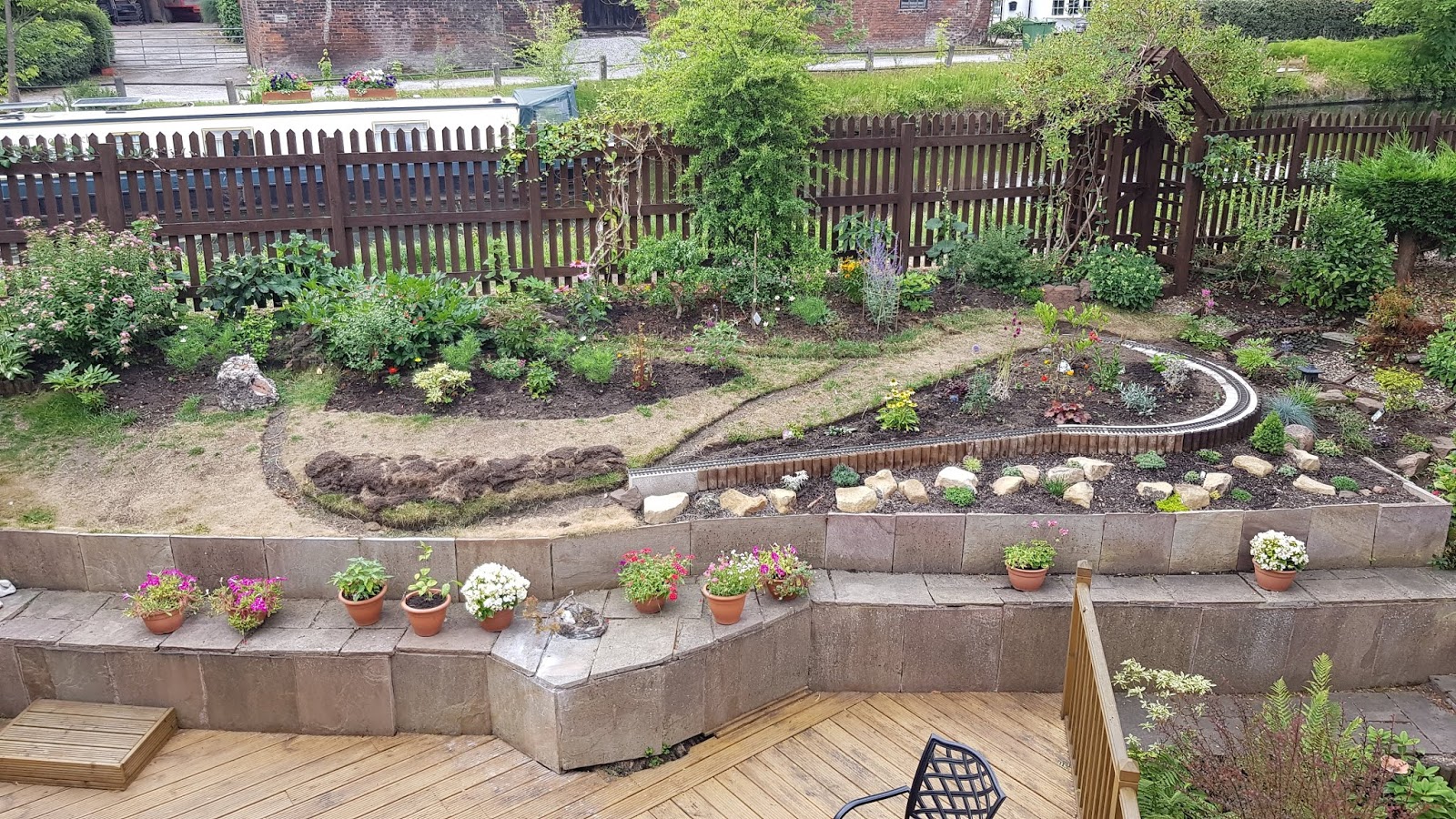
Mid March and the worst of the winter weather had passed. This is my canvas for the new Homestyal Light Railway. Two round axis markers were dug to help calculate the radius for the two ends of the layout (Photo 1).
Photo 2
The basic layout shape was scribed into the existing grassed area using a spade to a depth of approx. four inches. This was to be my outline during it's construction. The layout consisted of a loop and cross-over section. The terminal station will be at the front left of the loop, not yet scribed. (Photo 2).
Photo 3
The front straight section was made from concrete blocks with a depth of 140mm, sufficient for a single track line. I decided quite early on to use several construction methods with the idea, in time, to advise others of best method. The blocks were laid on to concrete as I went along, approx. two inches deep with additional concrete laid along the sides to the same depth. Once level and vertical they were left to set before mortar was added to the joints. Some of the joints have wooden blocks added to aid track pinning later. I found "Jenga" to be useful for this exercise. (Photo 3).

Sunday, 23 June 2013

Brookwood - The Foundations (Stage 1b)

With all the blocks laid and track purchased for this year, things are beginning to take shape down at Brookwood Station.

Looking northbound you can see the beginnings of the station platform (on the right) and the Ash and Repair Pit in the foreground.
The first three switches entering Brookwood will be motorised and operated via an MTS Switch Decoder LGB 55025, to be located in the signal box at the end of the platform.

If you zoom in, you can just about see the switch cabling already in situ.


Another view looking northwards.

Looking southwards with the station platform on the left you can see the fourth switch which will remain manual and sprung in favour of the returning locomotive.

Monday, 22 April 2013

Brookwood - The Foundations (Stage 1a)


With two and a half rows of blocks laid, the station foundations are almost complete. At the bottom of the photograph another three blocks will be laid at the end of row two for the line to continue to the Ash Pit, Repair Pit and the Maintenance Shed.


The five dwarf conifers will be relocated once the foundations for the Maintenance Shed have been laid. It will be at this point that the building work for the foundations will stop and recommence most probably during Spring 2014 when the foundations for the line to the Engine Shed will be laid.


Looking along the line from where the platform will be, towards Brookwood Bridge which can be seen in the distance.

Monday, 8 April 2013

Brookwood - The Foundations (Stage 1)

As the weather continued to be kind I set about laying the first foundation stones for the line into Brookwood Station.
Unlike the rest of the line I decided to use 100mm grey solid dense blocks for the foundations to give a flat and wide area for gradually developing the station and it's sidings, block by block. The initial block was laid at the point where the line ended last summer.


Each block was laid on a mixture of soil and 6mm limestone after the ground had been thoroughly tampered down with a small concrete brick to help prevent movement in the future. Between each block a 12mm gap was left and a 4:1 mortar mix applied. 


Each block was carefully checked for level and after each was laid, the overall level was checked. Any surplus mortar was pointed alongside each stone at the foundations.


Bit by bit the the blocks were laid for the station platform line, all the way to where the buffer stop will be.


The initial blocks were left overnight before the track was loosely laid and engine tested. Now I think I'll leave it a week to settle before adding the next lot of adjacent blocks.

Tuesday, 2 April 2013

Brookwood - The Location

At last with the weather improving, I can begin to create Brookwood Village. During the winter months, of which there have been plenty, I have managed to collect plenty of track and building supplies ready for the contractors, builders, track gang and their fellow wayside workers to commence.


This is the site for the new village, just in front of the ruins of an old church. Two leveling pegs have already been positioned on the left and middle of the photograph. The current 'end of the line' can just be seen on the right of the photograph.

Tuesday, 5 February 2013

Brookwood - The Plan


Based upon Llanfair Caereinion on the Welshpool & Llanfair Light Railway, this is what I have planned for Brookwood. There will be just one raised platform for passengers and a cattle and goods ramp behind the Engine Shed.

Track required

10000, G LGB 10000 Straight 300mm. 3
10090, G LGB 10090. Straight extendable 88mm-120mm. 1
10152, G LGB 10152 Straight separator 150mm. 1
10600, G LGB 10600 Straight 600mm. 13
10610, G LGB 10610 Straight 1200mm. 1
16000, G LGB 16000 Curve radius 1195mm, angle 22.5º(R3) 3
16050, G LGB 16050 Right turnout 440mm. 1
16150, G LGB 16150 Left turnout 440mm. 6
18000, G LGB 18000 Curve radius 2320mm, angle 15º(R5) 2

Saturday, 28 July 2012

Brookwood Extension - Diagonals

In between the rain, I managed to fit the diagonal struts to one side of Brookwood Bridge today.

The diagonals were fixed in place using the existing nuts & bolts and their respective holes used for the fixing of the horizontal and vertical girders.


A double diagonal strut was fitted to the mid-section.

Monday, 23 July 2012

Brookwood Extension - Update

The wayside workers were out this weekend laying more track between Brookwood Bridge and the village of Brookwood. Here's a quick update of where they are up to after Sundays work.

Looking south towards the bridge, the newly laid track can be seen cutting through the undergrowth.


Now looking north towards Brookwood.


Aerial shot of the progress.

Friday, 6 July 2012

Brookwood Extension - And the rains came!

With all this rain hitting the North West of England during the past twenty four hours, it was obviously a good idea to build this bridge!


Thursday, 7 June 2012

Brookwood Extension - Update

With the footings and supports in place, it was time for a quick alignment check. Everything was good, with both axis being perfectly level.


Although there is still plenty to do with regards to the modelling of the bridge, it was very pleasing to know that all was in order.

Diagonal struts, walk boards, painting and illumination have all still to be added.

Friday, 1 June 2012

Brookwood Extension - Girder Bridge footings (2)

With the warmer weather continuing I was able to complete the foundations for the bridge supports.

Once the foundations had dried, two concrete edging stones were mortared together and back filled with more concrete


After a couple more days the mortar and edging stones had set and the first track section, complete with signal, were positioned into place.


The support boards were removed too and the finished foundations left to completely dry before returning the excavated soil.


This method was used for both end supports.

Monday, 28 May 2012

Brookwood Extension - Girder Bridge footings (1)

With the dryer weather now upon us, it was time to begin the construction of the Brookwood Extension.

After the initial removal of a 10610 straight section (1200mm) replaced with an electric left switch 16150, a straight section 10600 (600mm) and two straight sections 10080 (82mm), it was time to lay the foundations for the new bridge supports.

The first bridge support foundations were laid to a depth of 175mm using spar, sand and cement to a 3:2:1 ratio.


Once the foundations have dried, after approximately 7 days, two concrete edging stones will be mortared together and back filled with more concrete. (See future post.)


Whilst waiting for the conctrete to dry, I covered the whole area with a solid plastic sheet to help the mix to slowly dry and thus not crack. (Not illustrated.)

Saturday, 5 May 2012

Girder Bridge - Stage 3

Using 10mm x 10mm angle aluminum the track supports were fixed in place with 3mm pan headed zinc plated screws.


The supports are slightly wider than the sleepers to allow for movement and expansion.


Friday, 23 March 2012

Girder Bridge - Stage 2

With both sides completed,  six 250mm lengths of aluminium were cut with 8mm holes drilled at each end and then connected to both sides across the top.


Similar to the top, five 250mm lengths of angle-aluminium were cut, again with 8mm holes drilled at each end and then attached to both sides across the base.


Next stage, track supports and side diagonals, angle permitting.

Wednesday, 14 March 2012

Girder Bridge - Stage 1

Clearing out my shed I came across my old greenhouse aluminium staging stand which had been dismantled and stored for many years. Should I throw it away, ebay it or..................make a girder bridge for an extension line?

I had also read one or two articles in railway magazines and viewed several clips on YouTube where girder bridges had been incorporated.

So I decided to give it ago and build one from scratch using the angle-aluminium and the nuts & bolts from the staging stand.

I knew that I needed it to be around 1800mm long by 250mm tall with a width for a single track of about 200mm.

So carefully utilising the pre-drilled holes wherever possible, I cut two bottom lengths of angle, two top lengths and sixteen vertical lengths. Loosely bolting the pieces together as I progressed, the first side began to take shape.
The top piece was added and the diagonals at each end were made to measure and again bolted together.


Here one side can be seen completed to stage one. The other side is made identical to this one.

Diagonals are yet to be added to each side provided that I have sufficient angle available.


Next stage, connecting the two sides together.